🔥 Single-Cell Abuse & Thermal Runaway Studio
Battery Simulator Web Studio
A precision multi-physics platform integrating Single Particle Model with Electrolyte (SPMe), 3D Finite Volume Thermal Networks, and 4-Step Chemical Exothermic Runaway Kinetics for Hot Box Oven Soak and Microscopic Internal Short Circuits (ISC).
🚀 Launch Simulation Studio
💡 Single-Cell Focus & Multi-Physics Architecture
This simulator is purpose-built to focus 100% on single-cell internal multi-physics and incipient thermal runaway (TR) mechanics , omitting cumbersome pack overhead.
Navigate smoothly across the 3 core tabs in the header: [SPMe Simulation] → [Cell Geometry & Thermal] → [Cell Abuse & TR] .
⚡ Tab 1: SPMe Simulation
Solves solid-state lithium diffusion and Butler-Volmer kinetics with electrolyte salt dynamics.
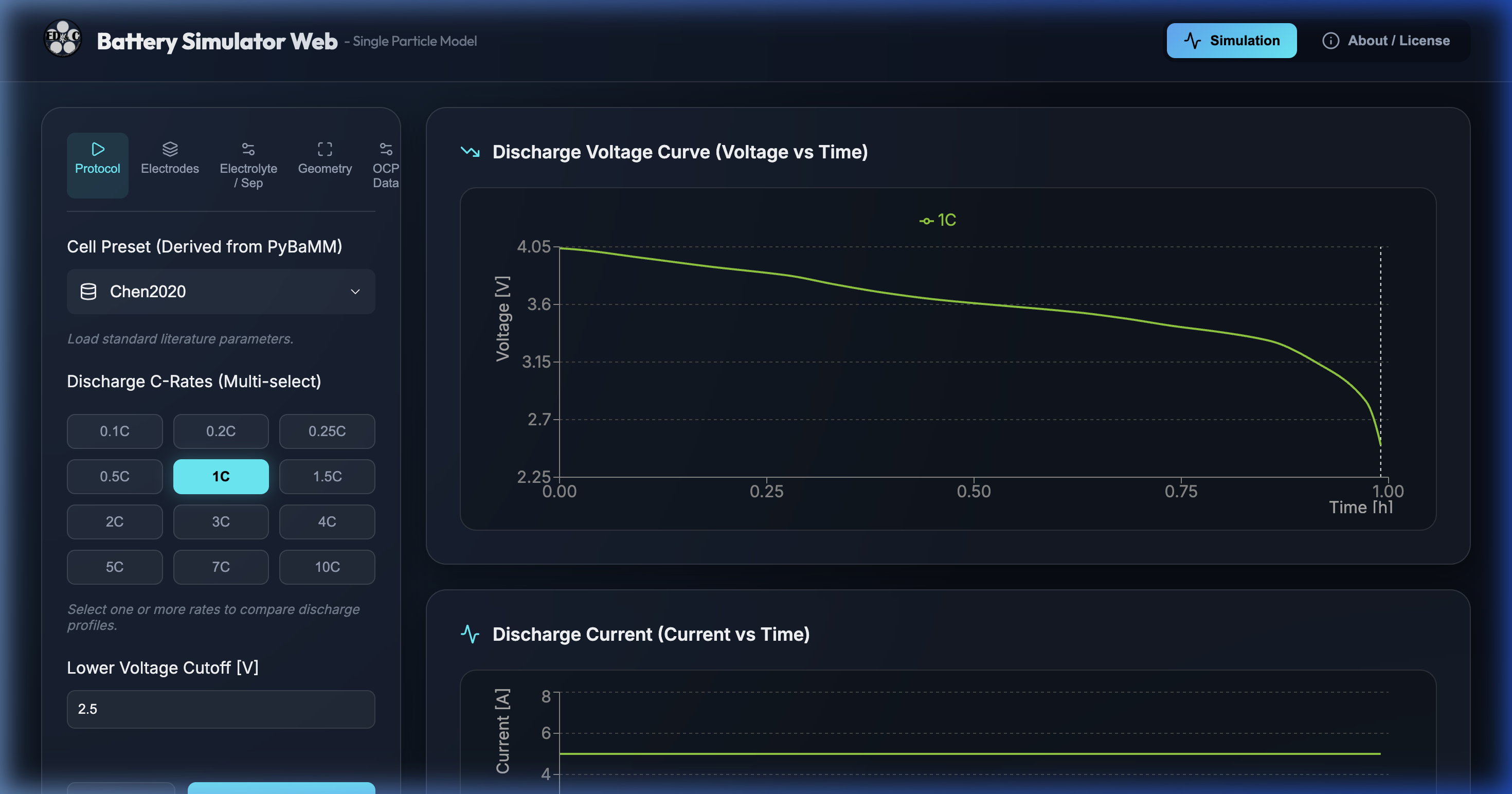
LG M50 Benchmark: Calibrated for LG Chem M50 21700 cell (5.0 Ah, NMC811 / Si-Graphite).Tabbed Parameter Inspector: Examine Positive/Negative electrodes, Separator, Geometry, and OCP tables.Dynamic Discharge Curves: View terminal voltage drops and overpotentials across various C-rates.
📐 Tab 2: Cell Geometry & Thermal
Configures physical dimensions, anisotropic thermal conductivities, and external convective boundaries.
Cylindrical Sizing: Customize outer diameter (21 mm), height (70 mm), and casing wall thickness (0.25 mm).Anisotropic Conduction: Separates radial jellyroll conductance (kr = 1.0 W/m·K) from axial foil conductance (kz = 25.0 W/m·K).Boundary Heat Dissipation: Adjust ambient temperature and convective cooling coefficient h .
🔥 Tab 3: Cell Abuse & TR
Investigates incipient thermal runaway under Hot Box oven soak and localized Internal Short Circuits (ISC).
4-Step Arrhenius Kinetics: SEI decomposition → Anode reduction → Cathode oxygen release → Electrolyte oxidation.Interactive 3D Cutaway: Inspect internal core hotspot formation and thermal propagation.Smart Early Termination: Automatically concludes after peak runaway observation, avoiding UI freeze.
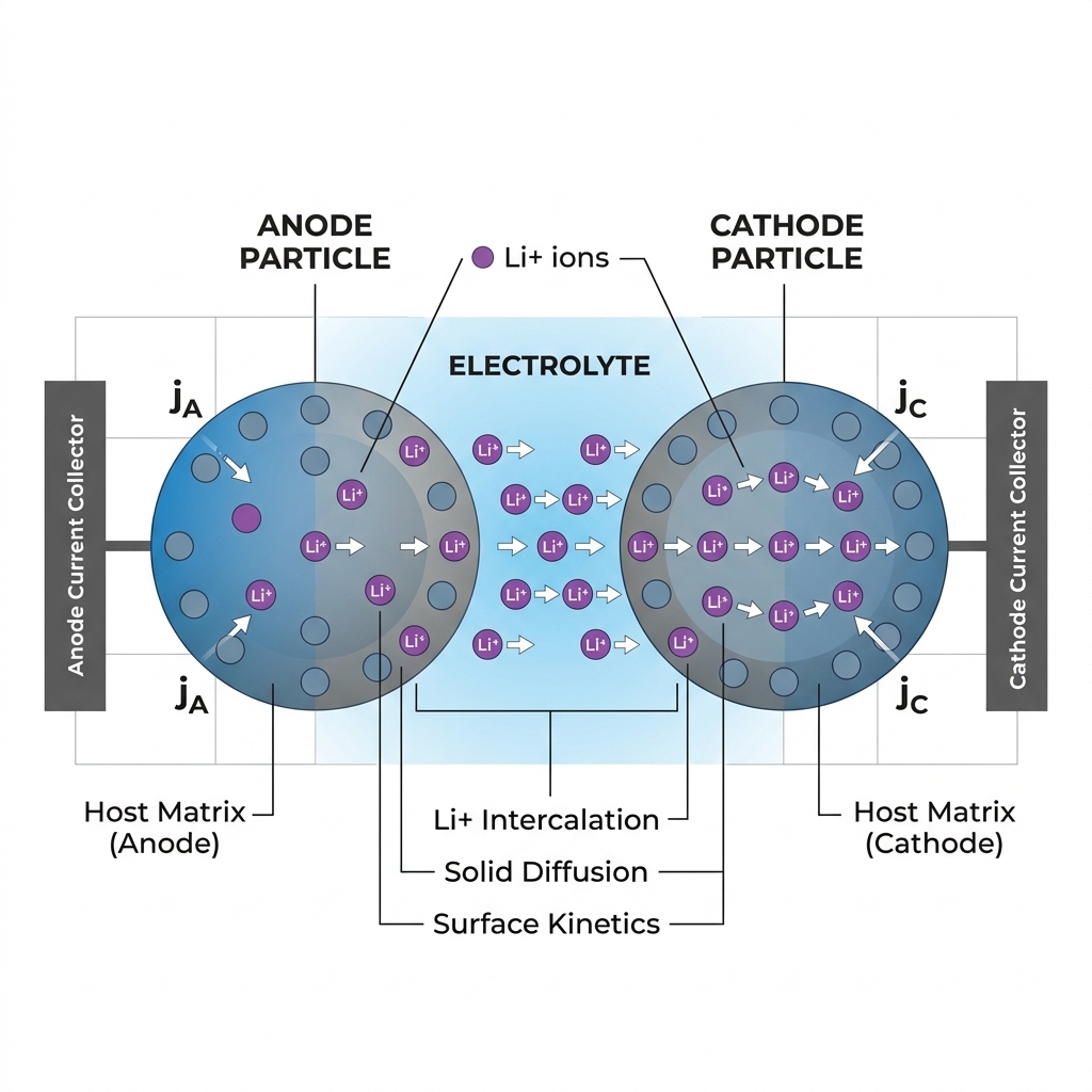
Figure 2: Microscopic architecture of Single Particle Model with Electrolyte (solid-phase diffusion & liquid transport)
Figure 3: SPMe Simulation studio interface displaying discharge curves and overpotentials
♨️ Protocol A: Hot Box Oven Soak Test
Soaks the cell in an elevated temperature chamber to assess intrinsic thermal endurance under UN 38.3 / UL 1642 standards.
Chamber Temperature: Default 150 °C (Configurable 100 °C – 200 °C).Convective Transfer (h): 15 W/(m²·K) oven convection.Thermal Balance: When SEI and anode side reactions exceed heat dissipation, self-heating accelerates past $T_2$ into Runaway.
⚡ Protocol B: Internal Short Circuit (ISC)
Recreates latent particle contamination, metal burrs, or lithium dendrite penetration across separator layers.
Sub-Grid Micro Hotspot: High current density concentrated in 5%–15% volume fraction triggers thousands of °C locally while bulk remains cool.Joule Heating Scaling: $Q_{\text{isc}} = V^2 / R_{\text{eff}}$. Lower short resistance drives exponential surge in current.
ISC Contact Mode
Interface Contact
Effective Resistance
Peak Current (4.2V)
Physical Mechanism & Severity
Type 1: Metal Dead Short Cathode Foil (Al) ↔ Anode Foil (Cu)
0.25 × (~0.025 Ω)> 160 A (~700 W)Direct metal-to-metal contact with negligible interface resistance. Extreme current triggers runaway in milliseconds.
Type 2: Anode Foil Short Cathode Active ↔ Anode Foil (Cu)
1.10 × (~0.110 Ω)~38 A (~160 W)
Moderate current limited by electronic resistivity of cathode oxide material.
Type 3: Cathode Foil Short Cathode Foil (Al) ↔ Anode Active (Gr)
0.85 × (~0.085 Ω)~49 A (~207 W)
Higher conductivity of graphite leads to elevated local heating compared to Type 2.
Type 4: Active-to-Active Cathode Active ↔ Anode Active
1.00 × (0.100 Ω)~42 A (~176 W)
Classic pinhole or dendrite penetration. Most prevalent real-world defect mode.
📊 Key Safety Metrics (KPIs)
Safety Outcome: SAFE (Self-healed / stabilized), VULNERABLE (Self-heating active), or RUNAWAY (Triggered $T_2$).T₁ (Self-Heat Onset): ~80 °C – 95 °C marking initial SEI decomposition.T₂ (TR Trigger): ~150 °C – 200 °C marking irreversible thermal runaway acceleration ($dT/dt \ge 1.0$ °C/s).Peak Core Temp: Maximum observed core temperature and peak rise rate.Total Heat Released: Cumulative Joulean and thermochemical energy release (kJ).
📈 Dual Waveform Analysis
Tab 1: Transient T(t) & V(t): Simultaneous trace of Core, Surface, and Micro-Hotspot temperatures alongside terminal cell voltage.Tab 2: Heat Mechanisms (W): Decomposed power curves showing Joulean short heat ($Q_{\text{isc}}$), SEI ($Q_{\text{sei}}$), Anode ($Q_{\text{anode}}$), Cathode ($Q_{\text{cat}}$), and Electrolyte oxidation ($Q_{\text{elec}}$).
Built with reference to open-source mathematical standards and peer-reviewed literature:
PyBaMM Framework: Sulzer et al. "Python Battery Mathematical Modelling (PyBaMM)." J. Open Source Softw. 6 (2021): 2980.LG M50 Parameters: Chen et al. J. Electrochem. Soc. 167 (2020): 080534.TR Chemical Kinetics: Feng et al. Energy Storage Materials 10 (2018): 246-267.ISC Physics & Scaling: Spotnitz & Hatchard. J. Power Sources 163 (2007): 1088-1097.
🚀 Launch the Multi-Physics Simulation Studio
Directly in your browser with zero server installation. Interactively explore SPMe electrochemistry, 3D cylindrical heat diffusion, Hot Box oven soak, and microscopic internal short circuits (ISC).
🚀 Launch Simulation Studio
💡 アプリケーションの構成と単セル特化について
本シミュレータは、過大なモジュール・パック計算を排し、「単セル(Single Cell)内部の微小熱電気化学現象と熱暴走(Thermal Runaway: TR)のごく初期兆候」 に100%フォーカスしています。
画面上部のタブバーから、目的とする解析フェーズへワンクリックでアクセスできます。通常は [SPMe] → [Cell Geometry] → [Cell Abuse & TR] の順に設定を確認・実行します。
① SPMe Simulation
電気化学・充放電特性解析
活物質拡散・過電圧・OCP・SOC
LG M50 (NMC811) 厳選プリセット
② Cell Geometry & Thermal
円筒セル幾何・3D伝熱メッシュ
外径/缶厚/高さ/異方性熱伝導率
コア(r=0) ⟷ 表面の温度勾配形成
③ Cell Abuse & TR
熱暴走初期・過酷試験解析
Hot Box (150℃) / 内部短絡 (ISC)
3D内部発熱・熱化学素反応連成
図1: 電子・物質移動(SPMe)から幾何伝熱(Geometry)、熱暴走化学反応(Abuse)への連成フロー
⚡ Tab 1: SPMe Simulation
単粒子電極モデル(SPM)に電解液相の塩濃度分布・液相過電圧を付加した SPMe(Single Particle Model with Electrolyte) を解きます。
厳選プリセット: 産業界の標準ベンチマークである LG M50(21700, 5.0Ah, NMC811 / Si-Graphite) を基本とし、LCO、LFPの正極系を網羅。パラメータ詳細表示: Positive / Negative 電極、Electrolyte / Separator、Geometry(極板面積・厚み)、および OCP(開回路電位テーブル)を閲覧可能。充放電プロファイル: 設定した C レートでの放電電圧曲線(V(t) )と過電圧成分の内訳をグラフ描画。
📐 Tab 2: Cell Geometry & Thermal
単セルの物理的寸法、熱容量、熱伝導率、および対流熱伝達条件を設定し、熱伝導方程式を解くための 3D FVM メッシュを構築します。
円筒幾何寸法: 外径(デフォルト 21 mm)、高さ(70 mm)、スチール缶肉厚(0.25 mm)を自由に微調整。異方性熱伝導率: ジェリーロール(巻回体)特有の性質である「径方向熱伝導率(kr = 1.0 W/m·K)」と「軸方向熱伝導率(kz = 25.0 W/m·K)」を個別設定。放熱境界条件: 外気温度(25℃)と表面熱伝達率 h (自然空冷 5〜10 W/m²·K)を指定。
🔥 Tab 3: Cell Abuse & TR
本スタジオの中核機能。外部過熱(Hot Box)または内部欠陥短絡(ISC)による 初期熱暴走(Incipient Thermal Runaway) をミリ秒単位でシミュレーションします。
4段階素反応モデル: SEI分解 → 負極還元 → 正極酸素放出 → 電解液酸化の過渡発熱を完全連成。3D リアルタイム可視化: クォーターカット断面表示で、内部ホットスポットから円筒全域への熱拡散を観察。スマート早期終了: 暴走確定後(ピーク通過直後)で自動打ち切り、無駄な長時間フリーズを防止。
図2: 単粒子電極モデル(SPMe)の物理構造(活物質粒子内リチウム拡散・液相輸送・界面電荷移動反応)
図3: SPMe Simulation タブの放電電圧特性・過電圧解析インターフェース画面
実機の安全性認証試験(UN 38.3, UL 1642, IEC 62133)で要求される外部加熱試験と、製造不良・デンドライト成長に起因する内部短絡試験の2大現象を再現します。
♨️ シナリオ A: Hot Box 試験(恒温槽過熱浸漬)
セルを一定の高温槽(オーブン)に投入し、外部加熱に対する熱的安定性と自発的熱暴走の有無を評価する国際規格試験です。
設定パラメータ:
Oven Chamber Temp: オーブン槽内温度(デフォルト 150℃、100〜200℃可変)
Heat Transfer (h): 槽内対流熱伝達率(15 W/m²·K)
Holding Duration: 恒温保持時間(最大 60 min)
熱物理メカニズム:
合否判定:
SAFE 、自発的暴走へ突入すれば RUNAWAY と判定。
⚡ シナリオ B: 内部短絡試験(Internal Short Circuit: ISC)
金属異物、電極バリ、またはリチウムデンドライトの貫通により、セル内部の極板間で局所短絡が発生する最重要危険事象です。
サブグリッド・マイクロホットスポット理論:
ジュール発熱則:
負極集電箔 (Cu)
負極活物質 (Gr)
セパレータ (PE/PP)
融点: 145 ℃
正極活物質 (NMC)
正極集電箔 (Al)
Type 4: 活物質 - 活物質 (Pin/Dendrite) [0.10 Ω]
Type 2: 負極箔(Cu) - 正極活物質 [0.11 Ω]
Type 3: 負極活物質 - 正極箔(Al) [0.085 Ω]
⚡ Type 1: 集電箔間直接金属短絡 (Al - Cu) [0.025 Ω, 160A+]
図2: セル極板積層構造における4種類の異物接触パターンと短絡経路
接触モード (ISC Type)
接触界面
実効抵抗比率
初期短絡電流 (4.2V時)
現象の特徴と想定異物事象
Type 1: 極限金属短絡 正極箔(Al) ⟷ 負極箔(Cu)
0.25 倍 (約 0.025 Ω)168 A 以上 (瞬間発熱 ~700W)金属バリ貫通、釘刺し試験。接触抵抗ほぼゼロのため数ミリ秒で1000℃超に達し最速で熱暴走。
Type 2: 負極箔接触 正極活物質 ⟷ 負極箔(Cu)
1.10 倍 (約 0.110 Ω)約 38 A (発熱 ~160W)
正極活物質の電子伝導性が律速となり抵抗高め。セパレータ融解まで比較的時間がかかる。
Type 3: 正極箔接触 正極箔(Al) ⟷ 負極活物質(Gr)
0.85 倍 (約 0.085 Ω)約 49 A (発熱 ~207W)
グラファイトの導電性が高いため Type 2 より低抵抗。早期に局所発熱が成長しやすい。
Type 4: ピンホール欠陥 正極活物質 ⟷ 負極活物質
1.00 倍 (基準値 0.100 Ω)約 42 A (発熱 ~176W)
リチウムデンドライト貫通や微小異物粉末。実機で最も発生頻度が高い代表的欠陥形態。
📈 動的抵抗モデル (Dynamic Model)
Expanding (拡大伝播型):
Fuse-like (自己溶断型):
Constant (固定抵抗型):
🎯 空間発生位置 (Location)
Core Center (r = 0):
Mid-Radius:
Outer Surface:
Top Tab Header:
⏱️ トリガー条件 (Trigger Method)
Initial Defect (t = 0):
Thermal (T ≥ T_melt):
Time Scheduled:
📊 主要安全性指標 (KPI Cards)
STATUS: 最終安全性結果判定。SAFE (放電終了またはヒューズ溶断で冷却)、VULNERABLE (自己発熱開始)、RUNAWAY (熱暴走発生)。T₁ (Self-Heat Onset): 自己発熱開始温度(約 70〜95℃)。SEI 被膜の分解開始温度を記録。T₂ (TR Trigger): 熱暴走臨界トリガー温度(約 150〜200℃)。昇温速度が 1.0 ℃/s を超え、不可逆的暴走に入った温度。Peak Core Temp: コア最高到達温度および最大昇温速度(℃/s)。Total Heat Released: 反応熱および短絡ジュール熱の総放出エネルギー(kJ)。
🎮 3D セル可視化 & 過渡ダイナミクスチャート
3D ビューア切替:
Quarter Cutaway : 1/4 断面を切り開き、内部ホットスポットと伝熱層を透視。
Metallic Casing : 実機同様のSUS缶外観を表示。
Thermal X-Ray : 半透明化して内部コア温度分布をダイレクト表示。
チャート 1: Transient T(t) & V(t):
T core )、表面温度(T surf )、短絡ホットスポット温度(T hotspot )、および端子電圧(V )の過渡変化を同時プロット。
チャート 2: Heat Mechanisms (W):
Q isc 、SEI分解 Q sei 、負極還元 Q anode 、正極分解 Q cat 、電解液燃焼 Q elec )の寄与度を過渡分離。
本シミュレータは、以下の世界的権威による電気化学モデルおよび熱暴走反応動力学の査読論文に基づき calibrated されています:
電気化学 SPMe モデル: Chen et al. "Development of Experimental Techniques for Parameterization of Multi-scale Lithium-ion Battery Models." J. Electrochem. Soc. 167 (2020): 080534.熱暴走素反応動力学: Feng et al. "Thermal runaway mechanism of lithium ion battery for electric vehicles: A review." Energy Storage Materials 10 (2018): 246-267.内部短絡モデリング: Spotnitz, R., and J. Hatchard. "Simulation of abuse tolerance for lithium-ion batteries." J. Power Sources 163.2 (2007): 1088-1097.短絡接触モード分類: Santhanagopalan et al. "Analysis of internal short-circuit in a lithium-ion cell." J. Power Sources 194.1 (2009): 550-557.デンドライト自己溶断特性: Orendorff et al. "Experimental tools for characterizing internal shorts in lithium-ion cells." Sandia National Laboratories Report (2011).