Automatically extract temperature-sensitive LTspice subcircuits from physical battery models. Give circuit designers the accuracy of electrochemistry without the computational overhead.
SPICE (Simulation Program with Integrated Circuit Emphasis) is the industry-standard software used by electronic and electrical engineers to design circuits like Battery Management Systems (BMS), motor controllers, and power supplies.
Circuit simulators cannot solve complex electrochemical partial differential equations (like the SPMe). They only understand basic electrical components: Resistors (R), Capacitors (C), and Voltage Sources (V). To simulate a battery in SPICE, we must translate its complex chemical behavior into an Equivalent Circuit Model (ECM).
This tool assumes you have already fitted the physical parameters (like particle sizes, porosities, and diffusion coefficients) using experimental data. It takes those physical parameters, runs a highly accurate electrochemical simulation, and mathematically extracts the corresponding electrical resistors and capacitors across all States of Charge (SOC) and Temperatures.
Instead of physically testing a battery for weeks to get its ECM parameters, this tool runs a "Virtual HPPC (Hybrid Pulse Power Characterization)". It subjects the physics model to short 10-second discharge/charge pulses followed by rest periods, precisely measuring the voltage response to calculate the exact Resistance and Capacitance at each step.
A standard ECM uses a series resistor ($R_0$) and one or more RC pairs (a resistor and capacitor in parallel) to represent the "lag" in voltage response. We use a 4-RC model because it directly maps to the physical origins of battery polarization:
By extracting these parameters independently from the Anode and Cathode potentials within the SPMe, we achieve a highly robust circuit model that behaves exactly like the physics model.
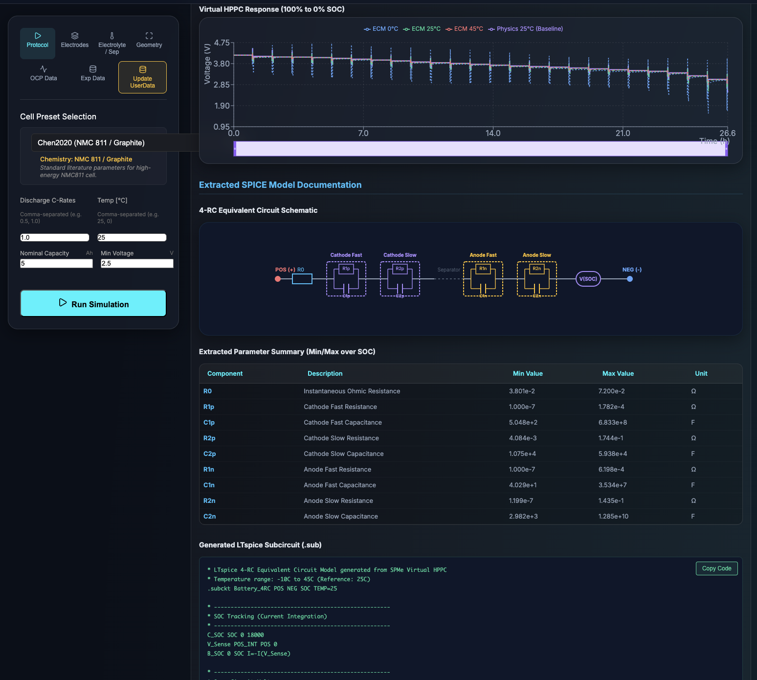
Once extraction is complete, the dashboard displays a graph comparing the baseline physics simulation (usually at 25°C) against the behavior predicted by the newly extracted ECM.
Crucially, the tool uses the Arrhenius Equation and extracted Activation Energies ($E_a$) to predict how the ECM will behave at low (e.g., 0°C) and high (e.g., 45°C) temperatures. You should see deeper voltage drops (higher resistance) for the 0°C ECM curve, validating that the SPICE model will react correctly to environmental changes.
The output text is formatted for LTspice. Here is a breakdown of what the code means:
POS and NEG are the electrical terminals. SOC is an output pin that provides a voltage representing the State of Charge (1V = 100%). TEMP is an input pin to define the cell temperature in Celsius.table() to look up their base value by SOC, and exp() to scale that resistance based on the TEMP pin (Temperature Dependence)..SUBCKT block and paste it directly into your LTspice library or schematic.SPICE (Simulation Program with Integrated Circuit Emphasis) は、電子回路や電気回路の設計(BMS、モーター駆動回路、電源など)を行う電子エンジニアが使用する業界標準のシミュレーションソフトウェアです。
回路シミュレータは、SPMeのような複雑な電気化学の偏微分方程式を直接解くことはできません。回路シミュレータが理解できるのは、抵抗 (R)、コンデンサ (C)、電圧源 (V) といった基本的な電気部品だけです。そのため、電池をSPICE上でシミュレーションするには、複雑な化学的挙動をこれらの電気部品に置き換えた等価回路モデル (ECM) に変換する必要があります。
このツールは、事前に実験データを用いて物理パラメータ(粒子径、空隙率、拡散係数など)のフィッティングが完了していることを前提としています。その精度の高い物理パラメータを用いて電気化学シミュレーションを実行し、すべての充電状態 (SOC) と温度における電気的な「抵抗」と「コンデンサ」の値を数学的に抽出します。
実機で数週間かけてHPPC(ハイブリッドパルス電力特性)試験を行う代わりに、このツールは物理モデル上で「仮想HPPC」を実行します。10秒間の短い充放電パルスと休止期間をシミュレーションし、その時の電圧応答を正確に測定することで、各ステップの抵抗とキャパシタンスを計算します。
一般的な等価回路モデルは、直列抵抗 ($R_0$) と、電圧の「遅れ」を表現する1つ以上のRCペア(抵抗とコンデンサの並列回路)を使用します。本ツールが 4-RCモデル を採用しているのは、電池の分極(電圧降下)の物理的な要因に直接対応させるためです:
SPMeシミュレーション内部の「正極電位」と「負極電位」から独立してパラメータを抽出することで、物理モデルと全く同じ振る舞いをする極めて堅牢な回路モデルを実現しています。
抽出が完了すると、基準となる物理シミュレーション(通常25℃)の電圧応答と、新たに抽出された等価回路モデル (ECM) の予測挙動を比較するグラフが表示されます。
重要な点として、本ツールは抽出した活性化エネルギー ($E_a$) とアレニウスの式を用いて、低温 (例: 0℃) や高温 (例: 45℃) でECMがどのように振る舞うかを数学的に予測し、重ねて表示します。0℃のECM曲線でより深い電圧降下(抵抗の増大)が確認できれば、生成されたSPICEモデルが環境変化に対して正しく応答することが視覚的に証明されます。
出力されるテキストはLTspice用にフォーマットされています。コードの主な構成は以下の通りです:
POS と NEG は電気的なプラス・マイナス端子です。SOC は現在の充電状態を電圧 (1V = 100%) として出力するピンです。TEMP はセルの温度 (℃) を指定するための入力ピンです。table() 関数を用いて現在のSOCに応じたベース抵抗値を参照し、さらに exp() 関数を用いて TEMP ピンの温度に基づくアレニウス・スケーリング(温度依存性)を適用します。.SUBCKT ブロックのテキストをコピーし、LTspiceのライブラリファイルや回路図に直接貼り付けて使用します。@misc{kusachi2025spmetospice,
author = {Yuki Kusachi},
title = {SPMe to SPICE (LTspice Battery Equivalent Subcircuit Generator)},
year = {2025},
url = {https://www.edandc.com/SPMeToSPICE/},
note = {YK Energy Device \& Consulting}
}