Can Pulse Charging Actually Charge Batteries Faster? What Happened When We Ran the Physics Simulations with AI
A Quick Note: Why We Tested This with AI
We often get questions from readers asking: "Can pulse charging really charge a battery super fast without degrading it?"
If you know a bit of battery basics, your first reaction is probably skepticism: "Wait, if you pause the charging current half the time, don't you have to push twice as much current when it is on? Won't that create way more heat ($I^2 R$)?"
Looking at tech news doesn't make it any clearer. Startups talk about smart pulse charging that cuts charging time, while a famous recent study from Germany (HZB) showed that 2 kHz pulses doubled battery life. It is easy to get confused because both are called "pulse charging," but they are actually doing two completely different things.
Since we couldn't find a simple, honest explanation anywhere, we decided to team up with an AI coding assistant, fire up an open-source battery physics simulator (PyBaMM), and run the numbers ourselves to see what really happens.
1. The Basic Question: "Doesn't Pausing Current Just Generate More Heat?"
Most of us who work with batteries are used to standard CC-CV (Constant Current / Constant Voltage) charging. If you try to fast-charge with a large continuous current, lithium ions can't enter the graphite anode fast enough. They pile up on the surface and turn into metallic lithium needles (plating), which can cause short circuits and degrade the cell. Also, the CV stage at the end takes forever because the current trickles down slowly.
Pulse charging fans often say: "If you insert brief pauses, the lithium has time to settle down and relax, so you can charge faster without plating!"
That sounds nice, but when you write down the basic math on paper, three awkward questions immediately pop up:
- If you want the same charging time, you must double the current: If you charge for half a second and rest for half a second (a 50% duty cycle), you have to push twice as much current during the ON time ($I_{\text{peak}} = 2 \times I_{\text{avg}}$) to get the same amount of charge into the battery.
- The heat doubles (Joule heating law): Heat generation depends on the square of the current ($P = I^2 R$). The effective root-mean-square current ($I_{\text{RMS}}$) goes up by $\sqrt{2} \approx 1.414$, so the average resistance heating is strictly doubled ($P_{\text{pulse}} = 2.0 \times P_{\text{CC}}$).
- Won't the battery hit 4.2 V even sooner?: When the current doubles, the voltage jump across the internal resistance ($I \times R$) doubles too. Wouldn't the battery hit its 4.2 V cutoff voltage much earlier, forcing you to slow down before the pauses have a chance to help?
2. Clearing Up the Confusion: Two Very Different Types of "Pulse Charging"
When we dug into patents and papers, we realized that people use the single phrase "pulse charging" to describe two completely different methods. That is why everyone gets confused.
Type A: Startup "Adaptive" Pulses (Qnovo, GBatteries, etc.)
These companies charge for a bit (hundreds of milliseconds to a second) and then pause for just a tiny fraction of a second (a few milliseconds). During this tiny pause, the BMS watches how the battery voltage relaxes. If a tiny bit of metallic lithium started to plate, the voltage holds at a flat plateau (~0 V) while it dissolves back into the graphite. By detecting this signal, the charger knows the exact maximum current it can push without causing permanent plating. In other words, the pulse waveform itself isn't doing magic—the pauses are used as a real-time sensor to drive the battery right at its physical limit and cut down the slow CV phase.
Type B: University High-Frequency Pulses (HZB 2024 Paper)
In 2024, researchers at Helmholtz-Zentrum Berlin (HZB) published a widely discussed paper showing that pulsing a commercial battery at 2 kHz (2,000 times a second) doubled its cycle life (81.7% capacity left after 1,000 cycles vs. 37.8% for normal continuous charging). Using X-rays, they showed that the pulses prevented graphite particles from cracking. However, it is crucial to note that this was NOT fast charging. The average current was kept at a standard 1C rate (1 hour charge). The study was about making batteries last longer during normal charging, not charging them in 10 minutes.
3. How We Set Up the Battery Simulation with AI
Standard physics-based battery models (the Newman P2D model) are usually designed for smooth, slow charging. They typically ignore the tiny capacitance at the electrode surface and don't simulate lithium plating and dissolving at the same time. To see what really happens during fast pulses, we worked with our AI coding partner to add three important features to the open-source PyBaMM framework:
Accounting for all currents at the negative electrode surface:
$$j_{\text{tot}}(x, t) = j_{\text{int}}(x, t) + j_{\text{pl}}(x, t) + C_{\text{dl}} \frac{\partial (\Phi_s - \Phi_e)}{\partial t}$$
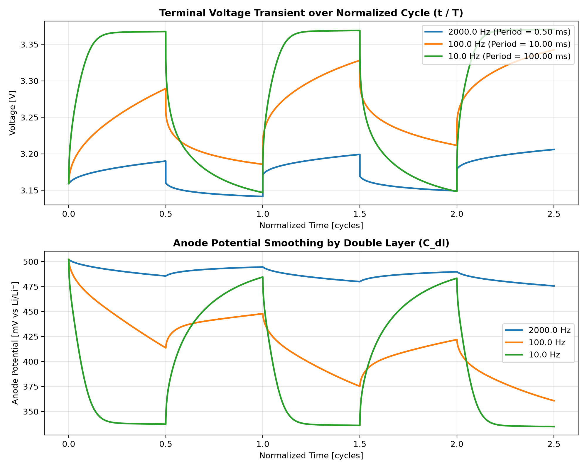
- Adding the Electric Double Layer (a tiny built-in capacitor): The boundary between the liquid electrolyte and the solid graphite acts like a tiny capacitor ($C_{\text{dl}}$). In our cell, this capacitor has a time constant of about 0.45 milliseconds (roughly 350 Hz). That matches the 2 kHz pulse (0.5 ms period) from the HZB paper almost perfectly! High-frequency spikes can bypass the chemical reaction and flow through this capacitor, cushioning the electrode.
- Letting Lithium Plate and Dissolve in Real Time: We allowed lithium to both slip into graphite ($j_{\text{int}}$) and plate on the surface as metal ($j_{\text{pl}}$). When the current pauses, any plated lithium naturally dissolves back into the graphite, creating the exact 0 V voltage plateau that BMS algorithms look for.
- Coupling Heat and Temperature Effects: Because pulsing generates extra heat, we coupled a thermal model with Arrhenius temperature equations. As the battery gets warm, ions move faster through the electrolyte and graphite, which helps lower internal resistance.
Deep Dive: How the Adaptive Current Logic is Implemented in PyBaMM
In standard PyBaMM, a simulation executes a predefined static script of commands (e.g., Experiment(["Charge at 10 A..."])). It has no built-in closed-loop BMS feedback controller to dynamically adjust current based on internal electrochemical potentials.
To replicate an adaptive closed-loop charging system, we developed a Block-Iterative Solver pattern (using starting_solution):
- Chunking into 10-Second Control Blocks: We divide the charging timeline into 10-second blocks. Each block runs 10 pulse cycles (0.95 s charge + 0.05 s diagnostic pause).
- Probing the Anode State: At the end of each block, the Python script extracts the negative electrode potential vs. Li/Li⁺ ($\Phi_s - \Phi_e$) and plating overpotential ($\eta_{\text{pl}}$) from the solver's internal state.
- Adaptive Step-Down Rule: If the anode potential drops below a safe buffer of $+10.0\text{ mV vs. Li/Li}^+$ (approaching the 0.0 mV thermodynamic plating line), the algorithm automatically steps down the charging current by 5% for the subsequent block: $$I_{k+1} = \max\left(2.5\text{ A}, 0.95 \times I_k\right)$$ If the anode potential maintains a safe margin, the current remains high (starting at 15.0 A = 3.0C).
- Seamless Physics Continuity: The subsequent block is solved via
sim.solve(starting_solution=sol). This passes all spatial lithium concentration profiles, double-layer capacitive states, and cell temperature continuously from the previous block without any numerical discontinuity or artificial reset.
4. Running Full-Charge Simulations: The Results
We simulated a standard 5.0 Ah 21700 cell (NMC811/Si-Graphite, commonly used in modern electric vehicles), starting empty (Initial SOC = 5.0%, 3.114 V, 25.0 °C room temperature). Using PyBaMM's fast IDAKLUSolver, we ran each protocol until it reached its practical operating limit.
Target Battery Cell & Parameter References (LG M50 21700)
To ensure real-world relevance, our simulation uses the widely studied commercial 5.0 Ah 21700 cylindrical cell (LG M50) parameterized with experimentally validated literature datasets:
- Format: 21700 cylindrical (21 mm × 70 mm)
- Volume & Surface Area: $2.42 \times 10^{-5}\text{ m}^3$, $0.00531\text{ m}^2$
- Cell Mass: ~68.0 g (Nominal Capacity: 5.0 Ah)
- Cathode: NMC811 ($75.6\ \mu\text{m}$, active fraction 0.665)
- Anode: Si-Graphite composite ($85.2\ \mu\text{m}$, active fraction 0.75)
- Separator: $12.0\ \mu\text{m}$, porosity 0.47
- P2D Parameters:
OKane2022parameter set based on Chen et al. (2020) with reversible plating kinetics from O'Kane et al. (2022). - Electrolyte Transport: $1.0\text{ M LiPF}_6$ in EC:EMC (3:7 wt%), Arrhenius conductivity $\kappa(c_e, T)$ and diffusivity $D_e(c_e, T)$ from Nyman et al. (2008).
- Heat Transfer: Convective cooling coefficient $h = 10.0\ \text{W/(m}^2\cdot\text{K)}$ (natural air cooling, $T_{\text{amb}} = 25.0\ ^\circ\text{C}$).
- Component Heat Capacities: Anode $700\ \text{J/(kg}\cdot\text{K)}$ ($\rho=1657$), Cathode $700\ \text{J/(kg}\cdot\text{K)}$ ($\rho=3262$), Cu foil $385\ \text{J/(kg}\cdot\text{K)}$ ($\rho=8960$), Al foil $897\ \text{J/(kg}\cdot\text{K)}$ ($\rho=2700$). Lumped heat capacity $C_{\text{th}} \approx 65\ \text{J/K}$ ($C_{p,\text{eff}} \approx 950\ \text{J/(kg}\cdot\text{K)}$).
How We Set Up the Simulation Runs (Safety & Rules):
To see what happens in a full charge rather than just a quick snapshot, we set up realistic operational rules:
- Thermal Safety Stop: If the cell hits 80.0 °C, stop charging immediately for safety.
- Standard Charging (Modes 0 & 1): Mode 0 is regular CC-CV (charges at 1C to 4.2 V, then holds until current drops to C/20; took 87.0 min to reach 95.7% SOC). Mode 1 is pure CC (cuts off as soon as voltage hits 4.2 V; took 43.3 min to reach 72.1% SOC).
- Simple Pulses (Modes 2C & 3): Because these don't track the anode potential, they must respect the usual 4.20 V voltage limit (plus the 80 °C temperature stop). Mode 2C hit 4.2 V early at 40.7 min because of the peak current voltage jump, finishing at 42.8 min (70.3% SOC, 41.6 °C). Mode 3 hit 4.2 V in just 18.6 min (finished at 21.9 min, 68.4% SOC, 62.2 °C).
- Adaptive Pulse (Mode 4): Because this tracks the negative electrode directly to avoid lithium plating ($> 0\text{ mV}$), we let the cell voltage go up to 5.0 V as a safety ceiling (stopping if temperature hits 80 °C). It reached 79.2% SOC (~80% fast charge) in just 16.7 minutes! However, cell temperature climbed to 69.9 °C (~70 °C), showing that heat is the real challenge.
| Mode / Protocol | Charge Pulse ($I_{\text{chg}}, t_{\text{on}}$) | Rest Pulse ($I_{\text{rest}}, t_{\text{off}}$) | Freq & Duty | Currents ($I_{\text{avg}} / I_{\text{RMS}}$) | Operational Boundaries | Charge Time & Final SOC | Min Anode Potential [mV vs Li/Li⁺] | EDR / SDG | Peak Temp $T_{\max}$ [°C] |
|---|---|---|---|---|---|---|---|---|---|
| Mode 0: Standard CC-CV (1.0C) | 5.0 A (1.0C), continuous | None | DC (100%) | 3.83 A / 3.83 A | 4.20 V Cutoff + C/20 (0.25 A) Taper Max Temp 80 °C |
87.0 min (SOC 95.7%) 80% at 49.1 min |
+5.87 mV | 0.525 / 5.19% | 36.93 °C |
| Mode 1: Pure CC (1.0C Cutoff) | 5.0 A (1.0C), continuous | None | DC (100%) | 5.00 A / 5.00 A | 4.20 V Cutoff (No CV phase) Max Temp 80 °C |
43.3 min (SOC 72.1%) Hits 4.2V Cutoff |
+5.87 mV | 0.525 / 5.19% | 36.93 °C |
| Mode 2C: 1 Hz Standard Pulse (1.0C-avg) | 10.0 A (2.0C), 0.50 s | 0.0 A, 0.50 s | 1.0 Hz (50%) | 5.00 A / 7.02 A ($\sqrt{2}\times$) | Upper Limit 4.20 V (Pulses clipped) Max Temp 80 °C |
42.8 min (SOC 70.3%) Hits 4.2V at 40.7m |
-14.88 mV (Transient dip) |
0.520 / 5.14% | 41.61 °C (+16.6°C rise) |
| Mode 3: Fast Pulse (2.0C-avg) | 20.0 A (4.0C), 0.50 s | 0.0 A, 0.50 s | 1.0 Hz (50%) | 10.00 A / 13.68 A ($\sqrt{2}\times$) | Upper Limit 4.20 V (Early clipping) Max Temp 80 °C |
21.9 min (SOC 68.4%) Hits 4.2V at 18.6m |
-20.10 mV | 0.811 / 11.25% (Salt depletion) |
62.23 °C (+37.2°C surge) |
| Mode 4: Adaptive Pulse (Closed-Loop) | Initial 15.0 A (3.0C) adaptive, 0.95 s | 0.0 A, 0.05 s (diagnostic rest) | 1.0 Hz (95%) | 14.25 A / 14.62 A | Anode tracking near 0V Ceiling 5.0 V, Stop at 80 °C |
16.7 min (SOC 79.2%) ~80% Fast Charge! |
-36.01 mV (Tracks 0V boundary) |
0.949 / 17.25% (Pore depletion) |
69.87 °C (Approaching 80°C!) |
Figure 1: Full-Cycle Electrochemical & Thermal Dynamics
Comparison across Mode 0 (CC-CV), Mode 1 (CC), Mode 2C (1 Hz Pulse), Mode 3 (Fast Pulse), and Mode 4 (Adaptive Pulse). Note that the second plot on the left displays the Negative Electrode Potential vs. Li/Li⁺ (Anode Potential); values staying above 0 mV indicate a thermodynamic safety margin against metallic lithium plating.
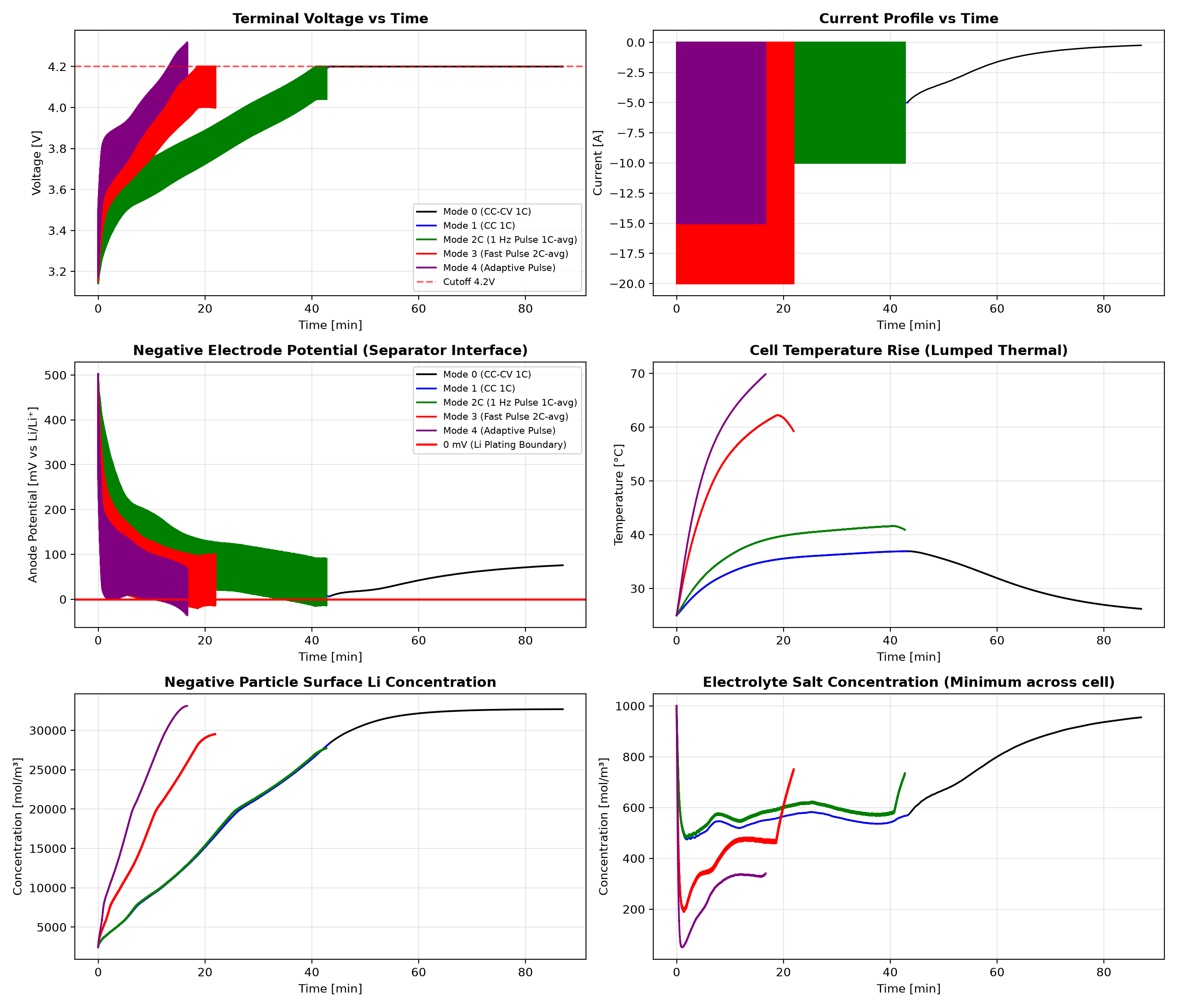
Figure 2: Micro-Transient Double-Layer Smoothing (2 kHz vs. 100 Hz vs. 10 Hz)
Normalized cycle ($t/T$) showing that at 2 kHz, the electrical double layer ($C_{\text{dl}}$) buffers square-wave current ripples, effectively smoothing the Negative Electrode Potential (Anode Potential vs. Li/Li⁺) and eliminating harsh interfacial stress spikes.
5. What We Learned: Honest Takeaways from an Engineer & AI
We are battery engineers and practitioners, not specialized simulation mathematicians. Running these physics calculations with AI was an eye-opening exercise. We aren't here to criticize any company's technology; real-world battery packs have many clever engineering tricks. Rather, these are the simple physical trade-offs we observed firsthand:
Takeaway 1: Pulsing really gets hot. But in cold winters, that might actually help!
Just as the basic physics predicted, 50% duty pulses produce twice as much heat as continuous charging ($P = I^2 R$). In our full-charge runs, the 1 Hz pulse cell (Mode 2C) reached 41.61 °C (+16.6 °C rise), and the fast adaptive pulse (Mode 4) surged to 69.87 °C (~70 °C) in just 16 minutes, getting dangerously close to our 80.0 °C safety cutoff.
This shows that even if smart pulse algorithms successfully prevent lithium plating, cooling the battery pack becomes the real bottleneck for fast charging.
On the flip side, in freezing winter weather (< 0 °C), this intense internal Joule heating could act as a built-in heater, warming up the cold electrolyte quickly without needing external heater pads.
Takeaway 2: Under a standard 4.2 V cutoff, simple pulsing doesn't make charging any faster.
The most practical lesson from Mode 2C was that if you stick to the usual 4.2 V voltage limit, simple pulsing gives zero speed benefit.
Because the peak current is doubled (10 A), the internal voltage drop ($I \times R$) is also doubled. The cell triggered the 4.20 V ceiling at 40.7 minutes—earlier than continuous CC charging (43.3 min). Both ended up at about 70–72% SOC in roughly 43 minutes.
This helped us understand what startups are really doing: their innovation isn't just "pulsing"; it's using the pauses to measure the anode potential so they can safely push past the conservative 4.2 V barrier without plating lithium.
Takeaway 3: The 2 kHz pulse really works as advertised—and could hold promise for future fast charging!
When we ran the numbers for the 2 kHz pulse from the HZB paper, the result was genuinely impressive.
At low frequencies (10 Hz or 100 Hz), the square-wave current hits the active particles directly, creating harsh voltage spikes. But at 2 kHz (2,000 Hz), the cell's built-in double-layer capacitor acts like a shock absorber. It smooths out the sharp corners into a gentle, rolling wave (Figure 2).
While HZB's experiment focused on doubling lifespan during a slow 1-hour charge, this physical cushioning effect is very real. If engineers can combine this with effective pack cooling, it could genuinely help pave the way toward safer, higher-rate fast charging in the future.
Takeaway 4: Did our simulations disprove the idea that "relaxation during rest enables fast charging"?
This is the core question every battery engineer wants answered. Looking squarely at our simulation data, the answer is: it was disproven for simple open-loop pulses, but conditionally validated for adaptive closed-loop charging. Here is the breakdown:
- Does relaxation actually occur during the rest periods? → YES, CONFIRMED
During the rest phase (even a tiny 50 ms pause), current stops and active particle surface overpotentials bounce back immediately toward equilibrium. If tiny amounts of metallic lithium had plated, it chemically dissolves and intercalates into the graphite, forming the flat 0 V relaxation plateau (visible in our Figure 1 anode potential plots). The local surface relaxation is physically real. - Does this relaxation allow a battery to charge faster under standard 4.2 V limits? → NO, DISPROVEN
The naive belief that "pulsing allows faster charging on any standard charger" was completely disproven by Mode 2C. To maintain average current with a 50% duty cycle, the peak current is doubled ($10\text{ A}$). The instantaneous ohmic jump ($I \times R$) doubles immediately, causing the terminal voltage to slam into the 4.20 V ceiling at 40.7 minutes—earlier than continuous CC (43.3 min). Furthermore, bulk electrolyte salt diffusion across the thick electrode requires ~52 seconds ($\tau_e = L^2/D_e$), so a 0.5 s pause is far too brief to reset macro concentration gradients. Constrained by 4.2 V, open-loop pulsing delivered zero speed advantage (42.8 min to 70% SOC vs. CC's 43.3 min to 72% SOC) while generating twice as much Joule heat. - Can relaxation enable fast charging when paired with adaptive BMS control? → YES, CONDITIONALLY
When the rest period is used as a real-time sensor to track the 0 V plating threshold and the artificial 4.2 V terminal ceiling is relaxed (Mode 4), the cell sustained high rates and reached 79.2% SOC in just 16.7 minutes without lithium plating. However, the simulation revealed that the fundamental bottleneck simply shifted: once the electrochemical plating limit was solved, the cell temperature surged to 69.9 °C (~70 °C). The limiting barrier for fast charging moves from the chemical realm to the thermal realm.
6. What This Model Can and Cannot Tell Us (Limitations)
To be completely transparent about our simulations and what we simplified:
- Simulating millions of pulses: Running a full 1-hour charge with 2 kHz pulses means calculating 7.2 million individual pulses. Solving that on a spatial mesh would take days on a desktop computer, so we separated the microsecond smoothing test from the macro full-charge runs.
- Particle cracking: We used concentration gradients inside the graphite particles as a rough indicator of mechanical stress. To directly predict cracking like HZB observed with X-rays, one would need to add full mechanical stress and fracture equations.
- Extreme salt depletion: When pushing very high currents, the salt concentration in the tiny liquid pores can drop close to zero, which makes the simulation solver struggle numerically.
7. References & Key Literature
- HZB Synchrotron Study (2 kHz Longevity): J. Guo, Y. Li, et al., "Operando Synchrotron Analysis of Lithium Plating and Intercalation Dynamics Under High-Frequency Pulsed Current," Advanced Energy Materials, 2024, 2400190. doi:10.1002/aenm.202400190
- P2D Degradation & Reversible Plating Baseline: S. E. J. O'Kane et al., "Physical origin of the differential voltage minimum associated with lithium plating in Li-ion cells," Physical Chemistry Chemical Physics, 24(13), 7909-7922, 2022. doi:10.1039/D2CP00417H
- LG M50 21700 Cell Parameterization: C.-H. Chen et al., "Development of Experimental Techniques for Parameterization of Multi-Scale Lithium-Ion Battery Models," Journal of The Electrochemical Society, 167(8), 080534, 2020. doi:10.1149/1945-7111/ab9050
- Arrhenius Electrolyte Transport Properties: M. Nyman et al., "Electrochemical Characterization and Modeling of the Mass Transport in LiPF6-EC:EMC Electrolytes," Journal of The Electrochemical Society, 155(9), A629-A635, 2008. doi:10.1149/1.2943228
- Adaptive Pulse Fast Charging Patent (Qnovo): D. M. Maluf et al., "Method and system for adaptive pulse charging of rechargeable energy storage devices," US Patent 9,787,122 / US Patent 11,237,216 B2.
- Active Pulse Charging with Stripping Detection (GBatteries): K. Timchenko et al., "Adaptive fast charging protocol based on dynamic impedance and overpotential monitoring," US Patent 10,218,200 B2.
If you found these physics simulations and technical insights helpful for your battery engineering workflows, consider buying me a coffee to support our ongoing open publications!
Cite This Article (BibTeX)
@article{kusachi2026pulsecharge,
  author = {Yuki Kusachi},
  title = {Can Pulse Charging Actually Charge Batteries Faster? What Happened When We Ran the Physics Simulations with AI},
  journal = {YK Energy Device \& Consulting Technical Insights},
  year = {2026},
  url = {https://www.edandc.com/articles/PulseQuickCharge_sim.html}
}